Work
Home | Work | Play | Photos | Contact | About
[Nakatomi] Payment System
Preface
The Payment System vision/scope presented below is a fictitious solutions concept for a fictitious company ([Nakatomi]), that calculates and makes payments to third parties. It's purpose is to demonstrate my consulting abilities, engaging with all stakeholders to formulate and drive project vision and scope, to elicit requirements and manage risk, thus enabling successfull outcomes for the client.
Whilst this document describes an imaginary payment system, it draws on my industry experience - from aerospace and defence, to retail, finance, public sector, telecommunications, and medicine, amongst others.
Any errors in this document are my own.
Contents:
1. Introduction
1.1. Purpose
The [Nakatomi] Payment System proposes the development a single solution that calculates and makes payments in response to payment requests from third-party payees.
1.2. Business Objectives
The payment system should:
- Provide a common registration system for payees
- Calculate and make payments to authorised payees.
- Provide management information
- Facilitate governance
- Leverage investments in the current IT estate.
- Generate n% savings through the reduction of manual processing
1.3. Technology Objectives
- The Payment System should leverage the [Nakatomi Trading Corp.]’s investments in Microsoft-based products, technologies and skills.
- The proposed solution should, where possible, make use of common off-the-shelf software (COTS).
- The Payment System should leverage [Nakatomi]’s existing Business Objects data warehouse.
- [Nakatomi] wishes to similarly leverage its investment in the SharePoint collaboration platform.
1.4. Quality Objectives
- Reliability - Reliability will be achieved through an auditable, idempotent messaging system as the core means of tracking payments. The system will ensure that all data transactions are atomic, consistent, isolated and durable.
- Correctness – A business rule engine will be used to verify the completeness and correctness of data within the Payment System. Hashing algorithms will be used to verify message integrity. Authentication and authorization will be used to control access to the system, and to create auditable activity logs. Data will also be encrypted, where appropriate, to meet data protection compliance requirements.
- Efficiency - Performance monitoring will be used to assess system-wide performance. The payment system will scale out as well as up to meet expected peak as well as unexpected loads.
- Usability – The system will make use of known and familiar user interface tools in use at [Nakatomi], to reduce the learning impact on users. The user interface will be consistent, unambiguous and intuitive.
- Flexibility – The Payment System will respect separation of concerns. This design philosophy allows individual system components to be upgraded or exchanged with no or minimal impact on other Payment System components.
- Interoperability – Component interoperability will be achieved through services-based messaging infrastructure, thereby creating a single system-public service contract which can be integrated with most modern technologies with minimal effort. The application will be based on service-oriented principles.
- Extensibility – The changing nature of the payment system will be accommodated by using templatized payment forms and meta-data. Business workflows and processes will be implemented using a customizable orchestration engine, and business rules will be enforced using a customizable business rule engine.
2. Conceptual Design
The diagram below depicts the conceptual architecture of the proposed Payment System. It identifies high-level system components and their relationships, discussed in greater detail below.
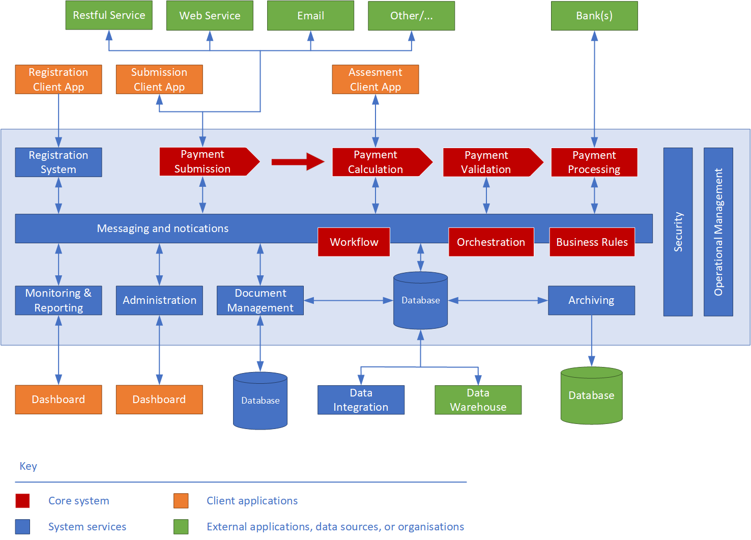
Figure 2.1 - Conceptual Design
The proposed solution consists of the following -
2.1. Client Applications
Client applications present user interfaces. They are web-based, and are to be hosted within the extant on-premises hosting environment.
- Registration Client – The Registration client application provides a user interface for payees to register themselves with [customer].
- Payment Submission Client – Used by payees to submit, correct and re-submit payment requests into the Payment System. The application also allows its users to monitor and track payment reuqestss within the system.
- Payment Assessment Client – The payment assessment client application is used by assessors, assessment committee members and domain experts to verify the correctness and completeness of payment requests identified as requiring manual validation. Users will also use this application to communicate with payees to resolve issues arising from incorrect or invalid payments.
- Monitoring Dashboard – The monitoring dashboard allows system administrators to monitor the solutions' health, and by management to obtain a real-time view of financial and operational performance metrics of the Payment System. The monitoring dashboard is also used to create and view reports.
- Administration Dashboard – Used by payment system administrators to manage payment templates, meta-data, and business rules. It monitors the technical performance metrics of the entire system. Administrators also use the dashboard to manage user accounts, and to generally ensure the smooth and continued operation of the system.
2.2. Server Applications
The application sub-systems implement [Nakatomi]'s core business processes required to manage, validate and process payment requests. Each system is implemented as a service with a distinct end point. Individual services are tied together using the messaging service (see below), which routes payment requests to the appropriate endpoints.
- Registration System – The registration system manages payee registrations.
- Payment Submission System – The payment request submission system manages the creation and initial validation of requests for payment. It also manages re-submissions of corrected requests. The payment request submission system is the single point through which payments can be entered into the Payment System.
- Payment Validation System – The validation system validates payment requests for correctness and completeness. The validation system routes appropriate requests to payment assessors for review, returns invalid requests to payees, and submits valid requests to the payment processing system.
- Payment Processing System – The payment processing system makes payments to payees.
- Messaging System – The overriding objective of the messaging system is flexibility – a message-based architecture allows workflow orchestrations to be changed in response to changing business requirements.
The messaging system provides a message routing service to all solution components. This allows other solution components to operate independently, thereby separating concerns of operation, and increasing system performance, extensibility, and flexibility.
This approach also facilitates the introduction of new components, or the exchange/upgrade of individual components within the solution without affecting other components.
Persisted messages may be XML-, JSON-, or other format suitable for use with EDRM.
2.3. System Components
System components manage general, cross cutting governance and security concerns for all components of the Payment System.
- Security – The security system provides payee registration, two-factor authentication, and authorization services to the Payment System. This component also provides data protection and auditing functions.
- Operational Management - these components allow business and technology owners to manage and monitor the overall health of the Payment System.
2.4. Information Architecture
Messages
The proposed solution is based on a messaging model, in order to provide the greatest flexibility and to support system extensibility. The collection of messages within the Payment System represents the state of the Payment System at any time. A message consists of an envelope containing message-handling meta-data, and the message payload (a payment request).
A message is unaware of its payload, which is encrypted. However, messages are routed based on the message-handling meta-data, which might indicate message state, its point of origin and destination, and the message access control list.
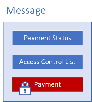
Figure 2.2 - Message Structure
The item type and status are used to route a message through the Payment System. Item types conist of -
- One-off payment
- Recurring payment
- Pre-approved
Status-based routing scenarios for messages include the following:
- Created – payment request routed to the payment submission system.
- Submitted – message routed to payment validation system.
- Approved – message routed to payment calculation system
- Referred – route message to auditor (the payment assessment client)
- Declined – route message to investigations (the payment assessment client)
Each message has an access control list, which authorizes access to the enclosed item, and an item status which, when changed, instructs the messaging system to route the message to the appropriate endpoint within the system.
A message can be saved to a database, or serialized to a file system. Because the message payload is encrypted, anyone opening a message cannot read its content without first authenticating him- or herself with the Payment System, and then being authorized by the access control list.
Payments
Payments vary in structure and content, based on payment type. Payment request forms may also change over time, and the workflow and business rules associated with payment request forms and payment validation may change over time.
To address the requirements of flexibility and extensibility, and in anticipation of later change requests, payments forms will be based on form templates. Templates describe the content of payments in terms of name/value pairs. The name provides a label for the value, which is entered by the payee. Name/value pairs can be linked to business rules, which are used to validate payments.
Payments also require meta-data, required to route payments, validate their content, and to apply payment rates during payment calculation.
Lastly, to facilitate payment assessment, payments must be annotatable, images and supporting documents must be added to payments as attachments, and a log must be maintained to track changes to a payment request over time.
This payment data, including its meta-data, is contained within a single logical entity. The entity is defined, as described above, by a template. The figure below provides a logical representation of payments, and the extensible template that defines them.
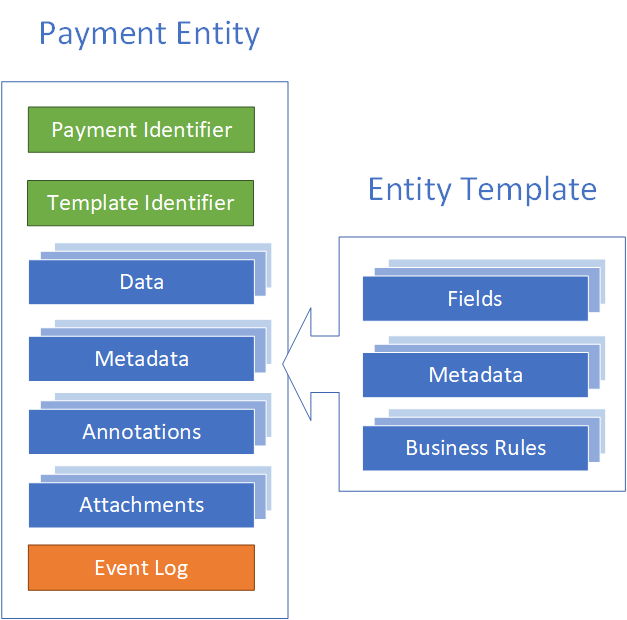
Figure 2.3 - Payment Structure
3. Logical Design
3.1. Architecture Overview
The logical architecture describes the components and the interactions required to build the solution. All client and applications will be based on the accepted application architecture archetypes, described below:3.2. Web Client Applications
Web applications enable browser-based access. The browser creates HTTP requests for specific URLs that map to resources on a Web server. The server renders and returns HTML pages to the client, which the browser displays. The core of a Web application is its server-side logic. The application can contain several distinct layers. The Payment System will make use of a typical three-tiered architecture comprised of presentation, application, and data layers. Figure 3.1 below illustrates a typical Web application architecture with common components grouped by areas of concern.
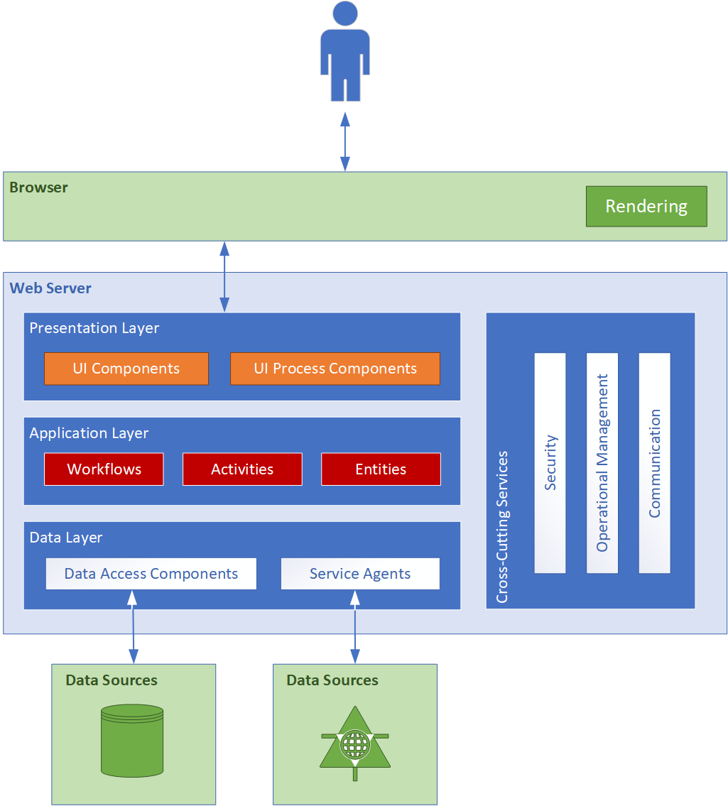
Figure 3.1 – Client applications
The Payment System contains the following web-based client applications, discussed in further detail in the sections that follow:- Registration client
- Payment request client
- Payment assessment client
- Monitoring and Reporting dashboard
- Administration Dashboard
3.3. Service Applications
A service is a public, typically web-based interface that provides access to a unit of functionality. Services provide programmatic functionality to the caller, who consumes the service. Services are loosely coupled and can be combined within a client, or combined within other services, to provide functionality that is more complex. Services are distributable and can be accessed remotely as well as locally.
Services within the Payment System are message-oriented, meaning that service interfaces are defined by WSDL files, and operations are called using Extensible Markup Language (XML)-based message schemas that are passed over a transport channel (the network). Services support a heterogeneous environment by focusing interoperability at the message/interface definition layer. Assuming a successful authentication and authorization, if components can understand the message and interface definition, they can use the service regardless of their base technology. Figure 3.2 below shows an overall view of the services application architecture proposed for the Payment System:
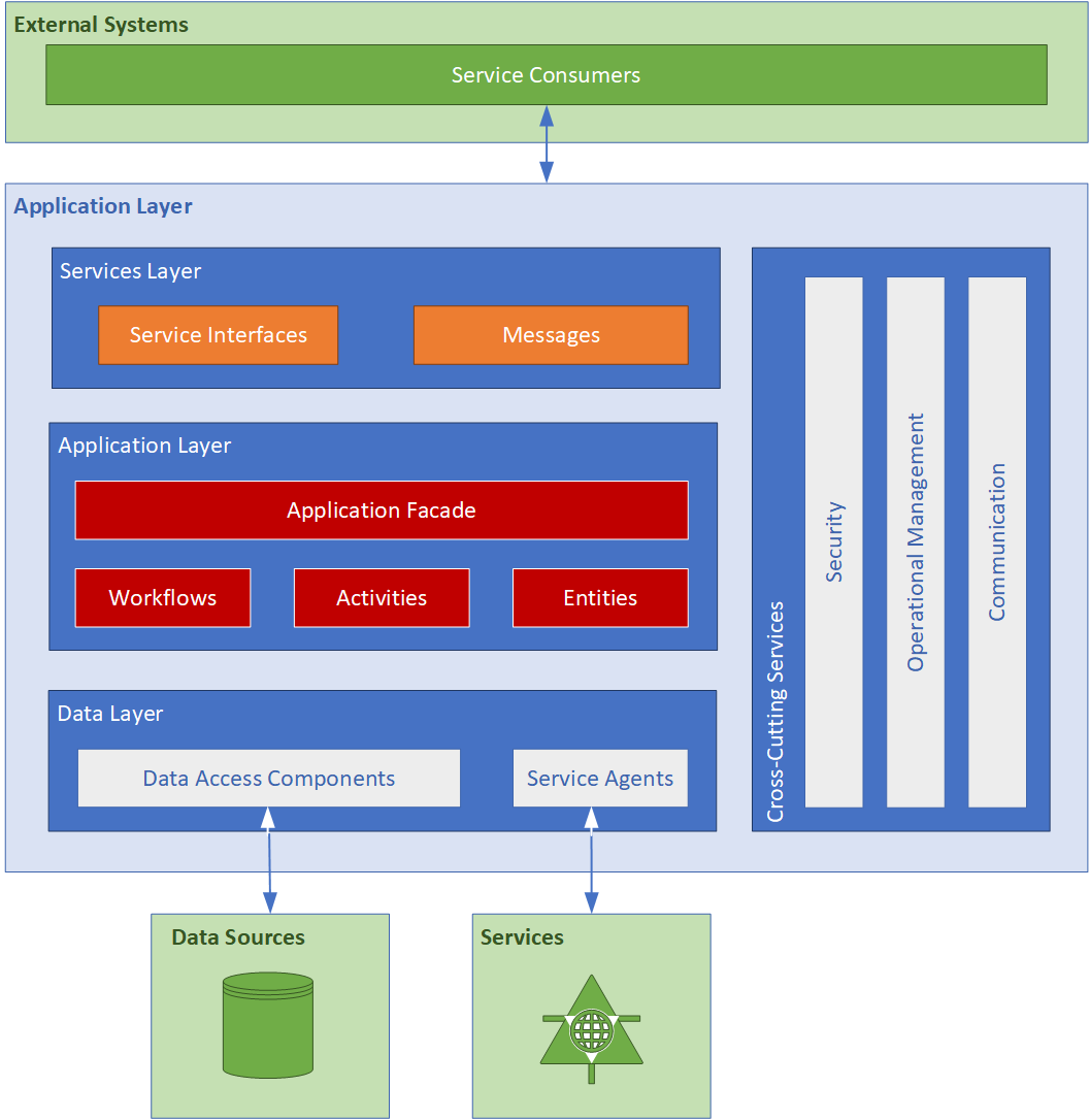
Figure 3.2 – Service applications
[Nakatomi]'s Payment System contains the following applications and services, discussed in further detail in the sections that follow:
- Registration System
- Payment Submission Service
- Payment validation Service
- Payment Processing Service
- Reporting Service
- Administration System
- Document and Record Management Service
- Archiving Service
3.4. Registration System
The Registration client application provides a user interface for payee registration.
3.5. Payment Submission Service
The Payment Submission Application is a multi-purpose web client application that allows its users to submit payments, correct and re-submit faulty payments, monitor payment progress through the system, and obtain financial and usage reports. The Payment Submission Application is a web application that consists of user interface, application and data access components. The application makes use of payment submission and validation workflows. It submits payments to the payment submission system (see section 3.7 below), and displays all notifications and reports required by payees, and their respective assistants or representatives to manage payments.
3.6. Payment Validation Service
The Payment Assessment Application is a web client application used by auditors to validate and verify the completeness and correctness of payments.
[Nakatomi]'s auditors use the Payment Validation Application to:
- Approve payments (approved payments are forwarded to the Payment System for processing)
- Send a message to a payee
- Refer payments to domain experts for verification
- Refer payments to review committee members for verification
- Reject payments (rejected payments are re-assesed and optionally re-submitted)
- Request contact with payee
In addition to the above, [Nakatomi]'s assessors use the Assessment Application to mark and annotate payments, add supporting documentation, view payment history, and to send messages to other stakeholders (other assessors, domain experts, amongst others).
The Assessment Application is a web application that consists of user interface, application and data access components. The application makes use of payment assessment and validation workflows. It retrieves payments from the validation system (see section 3.8 below), and displays all notifications and reports required by assessors to validate payments.
3.7. Messaging Service
This is the system that ties all Payment System components together. The Messaging System routes payments, messages and notifications, and supporting information between assessors, payment system, and supporting systems such as document management and archiving.
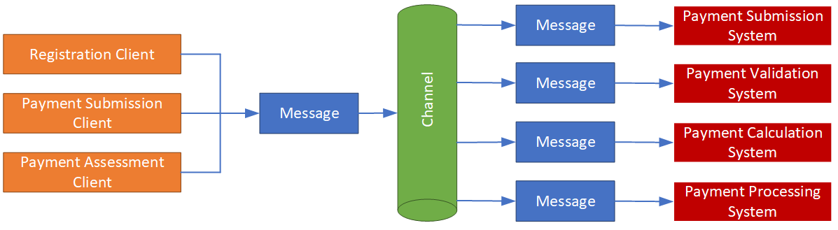
Figure 3.3 - Message Channels channel
As described in the Information Architecture above, messages contain two types of information – the message-handling meta-data and the message content (payload). A message is unaware of its payload. However, messages are routed based on the message-handling meta-data, which might indicate the state of the payment, the payment type, its point of origin and destination, and the message access control list.
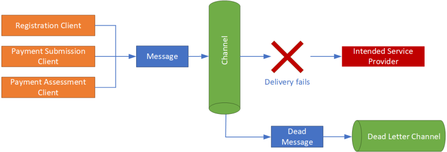
Figure 3.4 - Dead letter channel
The Messaging System makes use of the Security Service to encrypt and decrypt message content. It makes use of the Operational Management Service to log changes made to message content, and to log a message’s progress through the Payment System.
Messages that cannot be routed to an appropriate endpoint within the Payment System (due, possibly, to missing meta-data or unexpected message corruption) are sent to a dead letter channel, where an administrator can inspect the message and take appropriate action.
3.8. Registration Service
The Registration is responsible for on-boarding payees, and consists of tradional add/change/archive/delete functionaltiy.
3.9. Payment Submission Service
The Payment Submission Service accepts new and re-submitted payments from payees. The system also provides second-line, automated payment validation by checking payments for completeness and correctness. Payments that contain missing information are returned to the payee. Payments that meet its quality objectives, or require manual assessment, are forwarded to the Payment Validation System.
The Payment Submission Service also validates payments received from external systems, such as [External System Name].
A payment has a finite lifecycle – assuming all goes well, it is created, submitted, validated, submitted for payment, paid, and ultimately archived. The diagram below describes the payment lifecycle from a systems perspective, and shows the states a payment undergoes during its life cycle.
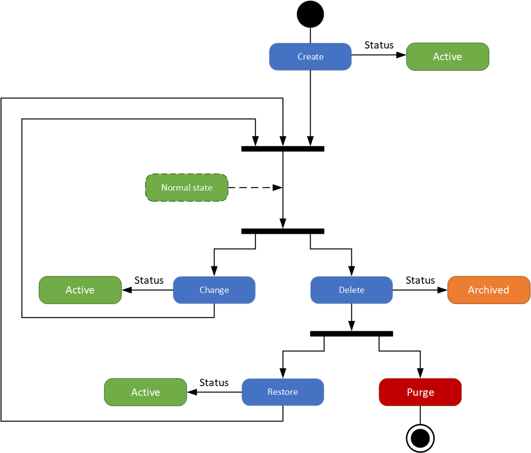
Figure 3.5 - Payment Processing System
The Payment Processing System effects payments based on payment instructions obtained from the Payment Calculation Service. Payments are submitted to the [AcmeBank] system for payment.
3.10. Monitoring and Reporting Application
The Monitoring and Reporting application is used by [Nakatomi] administrators to view system telemetry, and operational and financial reports.
3.11. Administration Application
The Administration Application is used by administrators to manage the Payment System. Payment System management includes:
- Ensuring the continued opeation of the Payment SYstem
- Maintaining payment templates.
- Mapping payment fields to business validation rules.
- Maintaining payment meta-data.
- Maintaining authorization levels.
- Maintaining business rules.
- Developing and maintaining system-wide risk register
- Generating and distributing business intelligence reports
3.12. Payment Form Builder
A form builder is required to create various payment types. The form-builder is used to create one or more payment templates to each payment type. The form builder will allow administrators uses to define payment data fields and required payment meta-data. The image below provides an overview of how such a form builder might look:
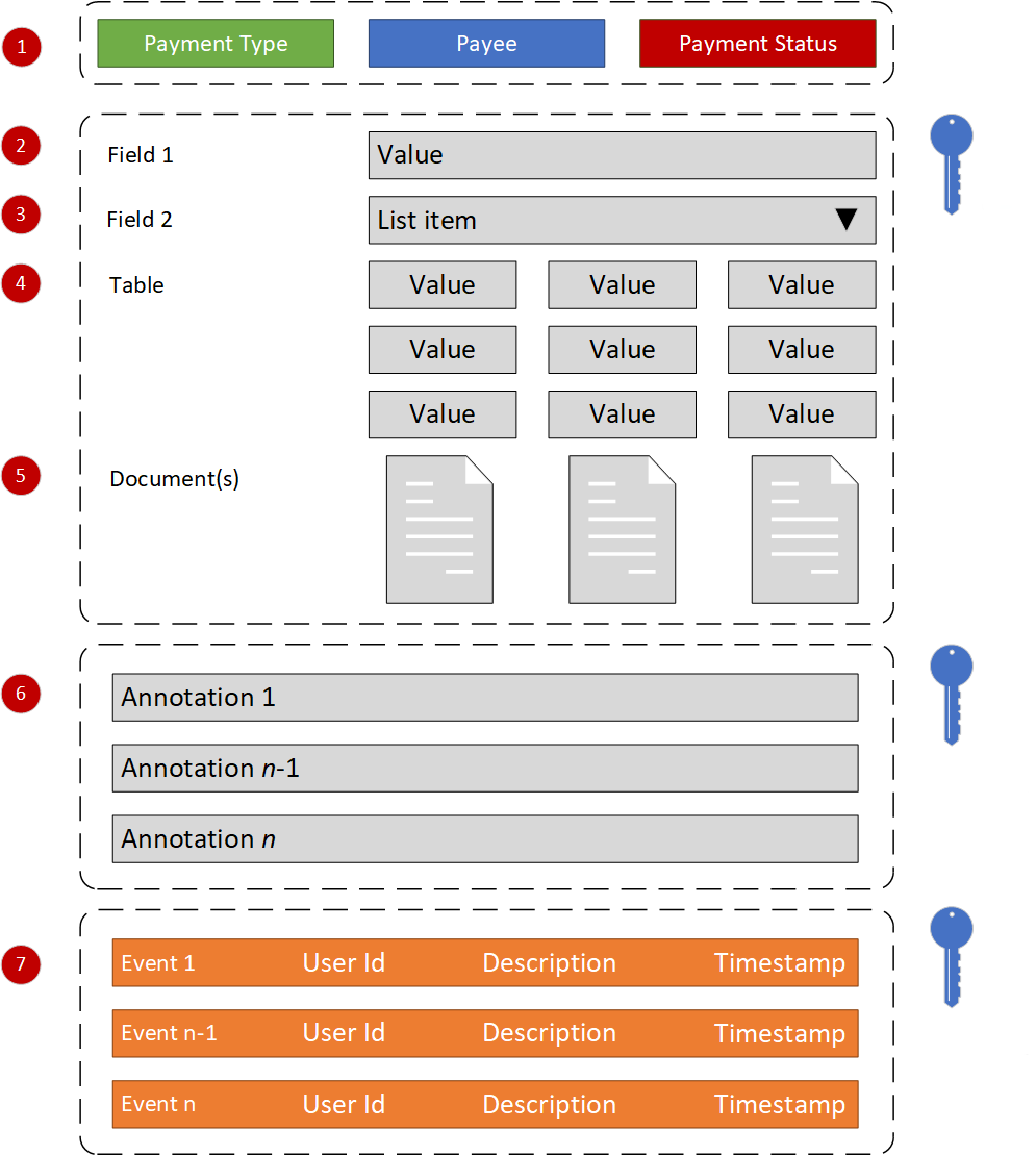
Keys indicate encrypted data.
Figure 3.6 - Payment Form Builder
- Tags – Tags desribe a payment’s meta-data. Tags are labels that have been linked to a payment form. The form builder facilitates the specification of optional and required label groups that are applied when a payment based on a valid template is created.
- Fields - Selection of a payment type label as described above will populate a payment form with fields (name/value pairs) based on the associated payment template.
- Field types – fields are simple name/value pairs, and can be alphanumeric, numeric, dates, yes/no fields, or lists, from which one or more items are chosen by the user.
- Tables – In order to present table data as sub-forms, such as payment header or payment details, the form builder must support tables, which are displayed as rows and columns.
- Attachments – The form will allow payment submitters and assessors to add documentation, images and other supporting files to the payment.
- Annotations – The payment form will allow payees and assessors to add comments and annotations to payments and/or their content.
- Event Log – All changes made to a payment are recorded in the payment audit trail (event log). The log identifies any changes made to payments, the source of the change, and the date/time/location of the change. Changes are digitally signed.
3.13. Document Management System
The Document Management System stores and tracks electronic documents used to validate and effect payments. It is also capable of keeping track of the different versions of supporting documentation created by submitters and assessors.
3.14. Operational Data Store
The Operational Data Store is used to aggregate data from multiple sources to support the payment submission, validation and payment calculation processes. Data in the Operational Data Store is shared with the Data Warehouse for reporting.
3.15. Data Integration Service
The Data Integration Service is responsible for aggregating, maintaining (where possible), and importing data required for the successful operation of the Payment System. The Data Integration Service imports data from external data sources, and/or provides real-time access to such data, depending on the capabilities of the external system the data is held in.
3.16. Business Intelligence
The Payment System will not provide Business Intelligence (BI) services. However, BI functions will be facilitated through [Nakatomi]'s existing data warehouse and BI capabilities. The Payment System will provide an appropriate connector or other data export mechanism to make its data available to the incumbent data warehouse.
3.17. Archiving System
The Payment System will not provide an archiving service. It will, however, make use of the BSO’s existing data archiving services.
3.18. Security
Security within the Payment System is multi-faceted – the term encompasses:
- Registration – refers to the creation of user accounts, as well as issuing a second authentication factor, such as a one-time password (OTP) key fob or smart card.
- Authentication – the mechanism used to determine that a Payment System user is who he or she claims to be. The Payment System uses two-factor authentication.
- Authorization – the mechanism used to determine what an authenticated user may do within the Payment System. This translates into a set of user permissions.
- Data protection – refers to the safe-guarding of data at rest and in transit. Data protection is accomplished through encryption.
- Non-repudiation – the logging mechanism used to provide an audit trail of user and system events within the Payment System.
3.19. Identity and Access Management
The Payment System will authenticate users using two-factor authentication. The authentication model is based on federated identities, in which the corporate authentication gateway, an identity provider external to the Payment System, is used to securely authenticate users.
To support the above, the Payment System issues identity cards and user accounts, and delegates authentication of users to the corporate authentication gateway. A trust relationship exists between the corporate authentication gateway and the Payment System.
In this approach, user account and smart card details are held in three systems –
- The provisioning system within the Payment System contains master records for authN and authR.
- The corporate, public authentication gateway holds user account and smart card details required to effect user authentication.
- The Payment System proxy in the Internet demilitarized zone holds the user account and a flag that indicates whether a given user account is active or not. This is a fallback mechanism that allows a Payment System administrator to de-provision accounts in the unlikely event that the corporate authentication gateway is unreachable.
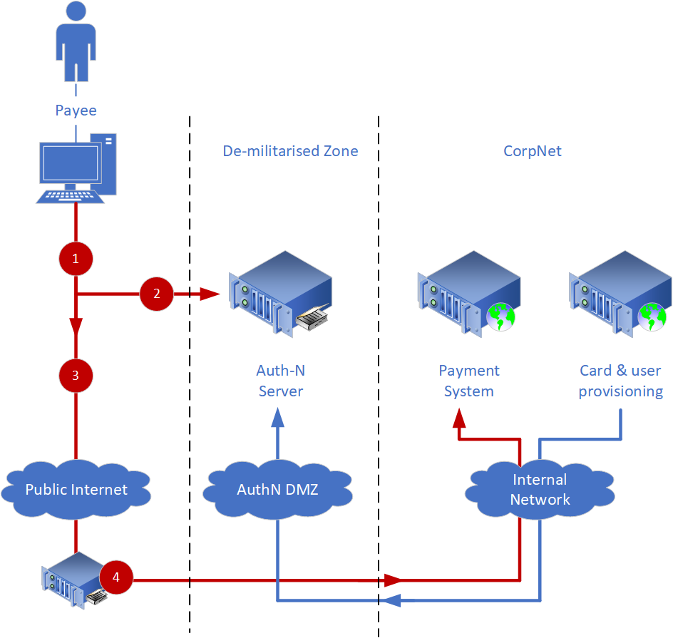
Figure 3.7
Using figure 3.7 as a reference, users are authenticated as follows:
- The user requests access to [Nakatomi]'s internet-facing Payment System, represented by proxy as Public Internet. The Internet DMZ looks for an authentication token to verify the user authentication.
- If no token is present in the request, the user is redirected to the Authentication server for authentication.
- The Auth-N server authenticates the payee using a two-factor authentication mechanism like Chip & PIN Claggenge/Response.
- If the authentication in step 3 succeeds, the payee is directed to the payment system.
3.20. User Account and Smart Card Provisioning
Again using figure 3.x above as a reference, users and smart cards are provisioned as follows:
- A user requests access to the Payment System. If access is to be granted, an administrator will create a user account, and issue a smart card and PIN to the user.
- The user account and smart card number are provisioned into the public authN server via a demilitarized zone.
- The user account is provisioned into the user directory in the Internet DMZ
The diagram below, and the text that follows describes the protocol used to provision and authenticate users.
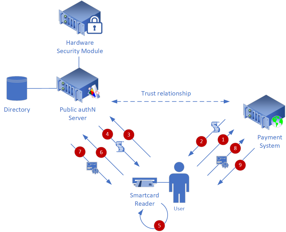
Figure 3.8
3.21. Authentication Process
A trust relationship exists between the identity provider and the Payment System. The steps required to authenticate for access to the Payment System are as follows:
- The user engages the Payment System by requesting access to the Payment System web site.
- The Payment System returns a policy which states that it requires the user to be authenticated and that it will consider for authentication only those subjects presenting an identity issued by the public authN server.
- The user then requests an identity from the public authN server.
- The public authN server verifies the existence of the user in its directory, and returns a policy that states that a two-factor authentication token is required to authenticate the user.
- The user completes a two-factor authentication using a smart card.
- The token issued by the smart card, if valid, is authorized by the public authN’s hardware security module (HSM).
- If the authentication is successful, the user receives an identity token from the public authN server.
- The user presents the token issued by the public authN server to the Payment System.
- The user is granted access to the resource requested in step 1 (the Payment System).
3.22. Operational Management
Operational Management components allow business and technology owners to manage and monitor the overall health of the Payment System. Operational management includes:
- Logging – all security and system events within the Payment System are logged, allowing audits to be performed, and also allows administrators to troubleshoot exceptions.
- Monitoring – the Payment System will provide real-time telemetry that indicates processing load, network performance and disk space usage, allowing administrators to proactively plan and manage system health.
4. Deployment
4.1. Logical Deployment Model
The logical deployment, shown below, shows how solution components are distributed across physical servers. To aid traceability the colours used in Figure 4.1 below correspond to those used for the same components in the conceptual design, described in Section 2 above.
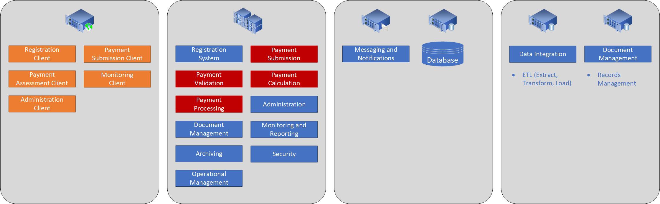
Figure 4.1
4.2. Physical Deployment Model
The (preliminary) physical deployment model shows how the solution might be deployed into a data centre. This model has been included to provide an indication of deployment scale,
and is subject to change in line with on-going project analysis. The Payment System will be deployed into both data centers, and will run in an active/active configuration. Web
servers will run on a separate network to the application servers. Individual servers within each data centre can be load-balanced, subject to load and performance metrics obtained
during testing.
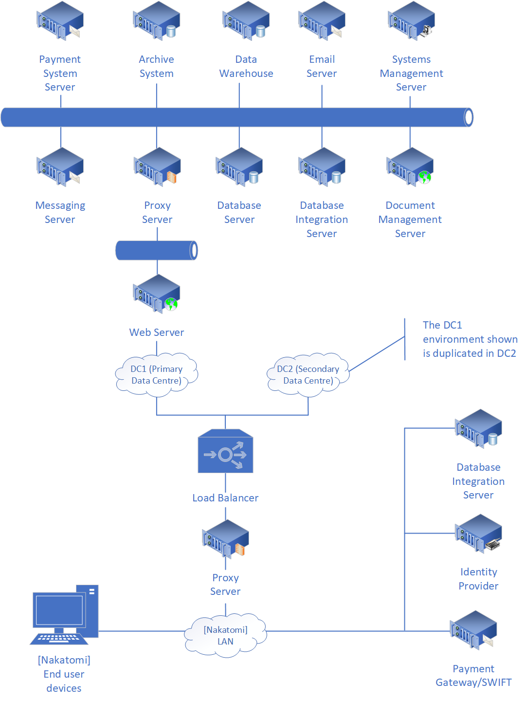
Figure 4.2.
5. Requirments Gaps
5.1. Payments
The SoURs (statement of user requirements) do not provide sufficient detail to construct meaningful payment forms. Sample payment forms indicating data structure, as well as sample payments for each type would produce a more coherent architecture and increase the accuracy of the estimate.
5.2. Registration System
Little is known about [Nakatomi]'s proposed payee registration system. The assumption is made that it is responsible for on-boarding and retiring payees.
5.3. Data Integration
Data integration end points described by this document have been inferred from the SoURs and additional research conducted online. However, a definitive list of external data sources would strengthen the architecture and increase the accuracy of the estimate.
Information required includes:
- The name of the end point
- The end point owner
- A description of the type of data the end point holds
- Access method (e.g. import, look-up or streamed)
- Access protocol (e.g. screen-scrape, remote procedure call (CORBA/COM/DCOM/Remoting, web service (SOAP/JSON), etc.)
- Access controls (authentication method, and authorization requirements)
- Data integrity controls that describe data accuracy, its update frequency and whether the Payment System can make changes to existing data.
5.4. Busines Rules
While many of the business rules required by the Payment System can be inferred from requirements, a complete or at least representative list or scope of business rules would be useful in driving the estimation process.
5.5. Payment Calculation
Little information about payment calculation rules and rates is available in the SoURs. The Statement of Financial Entitlement is available online, however guidance on whether this is the correct source of payment calculation rules, or not, is required. Additionally, it would save considerable effort and cost if the current rates and rules were already defined electronically, in a format suitable for use with a business rule engine.
5.6. Identity
In order to save development and operational cost, the assumption has been made that identity will be federated, and managed independently of the Payment System.
Consequently, the proposed architecture presented in this document assumes that an existing identity provider and smartcard infrastructure can be used.
6. Estimate
6.1. Project Schedule
| Project Day |
Milestone | Estimated Duration (Days) |
Cumulative Schedule |
Cumulative Effort |
|---|---|---|---|---|
| n/a | Start of feasibility study | n/a | n/a | n/a |
| n/a | Feasibility study complete | n/a | n/a | n/a |
| n/a | General requirements complete | n/a | n/a | n/a |
| 1 | Detailed requirements complete | 105 | 0% | n/a |
| 105 | High level design complete | 122 | 57% | 38% |
| 227 | Detailed design complete | 73 | 43% | 22% |
| 300 | Features/code complete | 122 | 57% | 38% |
| 422 | Start of user-oriented system test | 68 | 80% | 70% |
| 490 | Development and test complete | 37 | 93% | 89% |
| 527 | Payment system accepted | n/a | 100% | 100% |
6.2. Planning Options
The graph below contains planning options. They are derived from the nominal effort and schedule produced by the Monte Carlo simulation. Each of these options is considered to be equally achievable in the configurations shown.
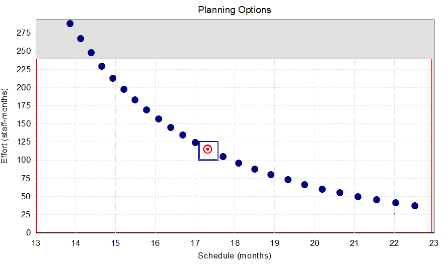
Figure 6.1
The nominal planning option, the planning option recommended before constraints and priorities are considered, is marked with a rectangle. The optimum planning solution, the option that best meets constraints and priorities, is shown in red. The non-shaded portion of this graph shows the range of schedule and effort solutions that are allowed under the specified schedule and effort constraints.
6.3. Constraints
Estimates can be constrained to hold results within numeric values for cost, effort, schedule, and peak staff. The table below shows the constraints used to create this estimate:
| Constraint | Value |
|---|---|
| Maximum schdule allowed | 24 months |
| Maximum effort allowed | 240 man-months |
| Maximum cost allowed | n/a |
| Maximum peak staff allowed | 20 |
6.4. Priorities
Priorities are used to determine the optimal project plan. The table below shows the priorities used to create the Payment System estimate:
| Priority | Value |
|---|---|
| Schedule | [not prioritised] |
| Effort | [not prioritised] |
| Cost | [not prioritised] |
| Peak staff | [not prioritised] |
| Mean time to defect (MTTD) | Absolute priority |
6.5. Estimate Quality
Estimates vary in the quality of assumptions used to create them. However, some of these characteristics can be evaluated programmatically. This estimate is rated using a five-point verbal scale:
- Excellent
- Very good
- Good
- Fair
- Poor
The overall quality of the estimate: Fair.
EOD.
![]()
All content copyright © Michael Wittenburg 1995 to 2025. All rights reserved.
Merch (t-shirts designed by my twin)